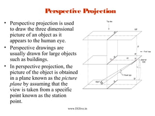
Engineering Drawing Graphics MED University of Engineering and Technology Peshawar 1 Lecture 03 Projections By Umer Farooq Mar 2019 THEORY OF ORTHOGRAPHIC PROJECTION 1. Perspective Projection Perspective projection is used to draw the three dimensional picture of an object as it appears to the human eye.
Lesson 13 Perspective Projection
Engineering Drawing slideshare net.
. Engineering Drawing Basics Explained. There are two basic types of projections. Projections and clipping in 3D.
Bhuiyan Shameem Mahmood 11 Engineering Drawing Introduction An engineering drawing is a type of technical drawing used to fully and clearly define requirements for engineered items and is usually created in accordance with standardized conventions for layout. PROJECTION A method to describe shape by the process of causing an image to be formed by rays of sight taken in a particular direction from an object to a picture plane. A perspective projection is quite useful in.
Parallel Projection is a type of projection where the line of sight or projectors are parallel and are perpendicular to the picture planes. The first one is the perspective projection in which the projectors are starting from a pointobservers eye to each point of part. The other projection type is the parallel projection in which the projector lines are parallel to each other.
However for conventional engineering drawing drawing in perspective is an unnecessary complication and is usually ignored. Reprographics engineering drawing sketching pictorial projections paper sizes scales. Perspective 2-Point perspective drawing STEP 6 Draw 2 lines from the SP that are parallel to the bottom edges of the Plan View Fig 6.
THE MANAS PATNAIK LIBRARYTopic-wise Playlist of Engineering Drawing Engineering Graphics in English1. Explains the Basics of Engineering Drawing. Projections Projections transform points in n-space to m-space where m n.
ENGINEERING GRAPHICS 1E9 Lecture 5. A pictorial perspective or simply perspective projection is drawn so that parallel lines converge in the distance as shown in Figure 22 unlike isometric or trimetric pro-jections where parallel lines remain parallel. Projections - engineering drawing.
An Isometric Projection is one type of pictorial projection in which the three dimensions of a solid are not only shown in one view but also their dimension can be scaled from this drawing. This projection type is more useful in engineering-level technical drawings because the exact. Draw the perspective projection of a pentagonal prism of side 25mm and height 50mm lying on one of its rectangular faces on the ground plane and one pentagonal face touching the picture plane.
Iso means equal and metric projection means a projection to a reduced measure. PERSPECTIVE PROJECTION ProfTJEYAPOOVAN Department of Mechanical Engineering Hindustan Institute of Technology and Science Chennai-603103 India wwwEGlivein 2. Seven illustrations no1 to 7 draw different orthographic views 6.
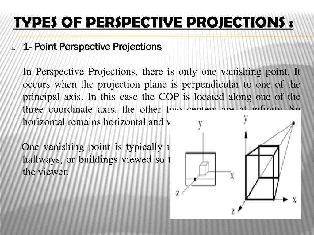
Viewing and projection Objects in WC are projected on to the view plane which is defined perpendicular to the viewing direction along the zv-axis. Types perspective projection this is the type of pictorial projectionin which all the projectors meet at a point is known as perspective projectionthis projection does not re-persent actual size of the object by given general out look. Engineering Graphics- Basics - Engineering Graphics- Basics By MrBRamesh ME PhD Research Scholar CEG Anna University Chennai.
The learning objectives of this presentation are. Engineering Drawing - Free download as Powerpoint Presentation ppt PDF File pdf Text File txt or view presentation slides online. The station point is 55mm in front of the picture plane and lies in the central plane which is 75mm to the left of the center of the prism.
Isometric Projection l w h. Are drawn as multi view drawings which show flat representations of principal views of the subject. Technical communication report writing drawing Contents.
The problem in perspective projection is due to the single station point that produces radiating projectors. The projection in which show the lengthbreath and height of an object is known as pictorial projection. 1st angle method - illustration 3.
It is subdivided in to the following three categories. Orthographic projection is widely used for fabrication and construction type drawings as shown in Figure 1. 3rd angle method illustration 4.
Total nineteen illustrations no8 to 26 Page 3 Orthographic Projections - Basics 1. To recognize colored surfaces and to draw three Views 5. This makes understanding the drawings simple with little to no personal interpretation.
Following are the principles of Perspective Projection. The two main types of projection in Computer Graphics are. The vertical axes of the drawing are shown perpendicular.
Projection sets two sides of the cube usually those of the front face equal. The horizontal lines of the drawing look to meet at a point called Vanishing Point. Parallel projection perspective projection.
The purpose is to convey all the information necessary for manufacturing a product or a part. To equip students with basic skills required in engineering drawings electrical circuit diagrams and communication. Principles OF Perspective Projection.
Course Purpose and forms of communication. To study concept of principle. Perspective drawings are usually drawn for large.
Thus perspective projection is very rarely used to draw engineering objects. Other views such as a bottom view are used to more fully depict. Academiaedu - Share research.
An engineering drawing is a subcategory of technical drawings. Disadvantage of Perspective Projection Perspective projection is not used by engineer for manufacturing of parts because 1. Engineering drawings use standardised language and symbols.
Engineering Graphics I - Department of Applied Sciences Engineering - This presentation covers various topics from Engineering Graphics and is presented by Professor Yogiraj Deshmukh from the department of Applied Sciences and Engineering at International Institute of Information Technology I²IT. Orthographic projections present the component or system through the use of three views These are a top view a side view and a front view. There are two projection methods Perspective Parallel Projection theory comprises the principles used to graphically represent 3D object and structures on 2D media Projection Theory Orthogonal Views 2D Pictorial View 3D Projection Methods Projection Methods Parallel Projection Oblique Orthographic Axonometric Isometric Perspective Projection Dimetric Multi-View.
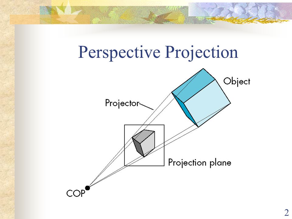
Orthographic Oblique and Axonometric Projections. The vanishing points are shown on the horizontal lines in the System of Horizontal Lines. W Perspective - distance from COP to PP finite w Parallel - distance from COP to PP infinite.
In 3D we map points from 3-space to the projection plane PP along projectors emanating from the center of projection COP. Explanation of various terms 2.

Perspective Projection Concept And One Point Perspective Part 1 Engineering Drawing Youtube
Perspective Projection Ppt Download
Ppt Perspective Projection Powerpoint Presentation Free Download Id 4523251

Ppt Perspective Projection Powerpoint Presentation Free Download Id 4523251
Ppt Perspective Projection Powerpoint Presentation Free Download Id 4523251

Me 142 Engineering Drawing Graphics Projection Method Ppt Download
1 Chapter 5 Viewing 2 Perspective Projection 3 Parallel Projection Ppt Download

Unit V Perspective Projection
0 comments
Post a Comment